Wiring Diagram Capacitor Start Motor
If you don’t see what you’re looking for, please. Connect the condenser fan to the existing start device.
☑ How To Replace Electric Motor Capacitor
Wiring Diagram Capacitor Start Motor. Web when it comes to a wiring diagram for a capacitor start motor, there are several components to take into consideration. Web single phase capacitor start motor wiring diagram. In this circuit, there is only one load for each line between l1 and l2, even though there are two loads in the circuit.
Click Here To View A Capacitor Start Motor Circuit Diagram For Starting A Single Phase Motor.
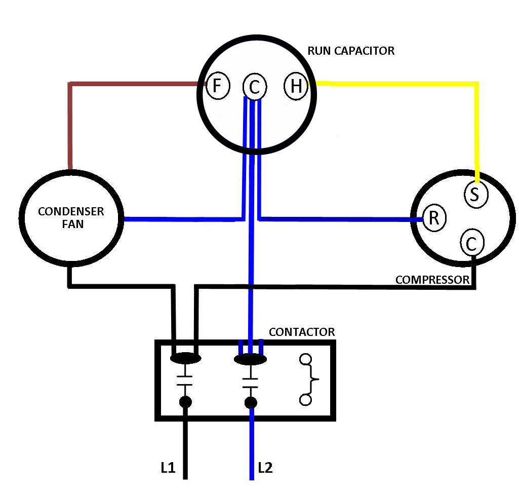
They are known as the main winding and the auxiliary or the starting winding. Web those contacts attach to the solenoid’s “b” and “m” terminals. Push the wire terminal on the start capacitor's second wire onto the run capacitor's common terminal, often labeled c, com. the wire connected to the motor's run terminal, marked as r on the motor's wiring chart, and the wire going to the hot terminal on the load side of the contactor also connects to this run capacitor terminal.
Web Single Phase Capacitor Start Motor Wiring Diagram.
The reason the start winding has high dc resistance is the series start capacitor. Faqs about wiring a starter. However yellow is the start switch blue is the auxiliary winding and red is the main winding.
Web Split Phase Permanently Connected Capacitor Electric Motor Wiring Diagram.
Web the phasor diagram of the capacitor start motor is shown below: If the cover from the compressor relay/start device is removed, you should find three pins for the unit, labeled r, c, and s. The wiring colours to the motor suggest that this is a three phase motor, just to confuse me.
The First Component Is The Electrical Power Source, Which Could Either Be A Wall Outlet Or A Battery.
Now we will learn about the single phase motor 2 capacitor wiring diagram or capacitor start capacitor run motor. You can discharge a capacitor by placing an insulated screwdriver across the terminals. Other essential parts of a capacitor start motor include the capacitor, the motor itself, the motor starter, and any relays.
A Capacitor Start Capacitor Run Motor Is Also Known As A Two Value Capacitor Motor.
The diagram is often divided into sections to make it easier to read and interpret. Dve motors feature capacitor start and run making them suitable I m is the current in the main winding which is lagging the auxiliary current i a by 90 degrees as shown in the phasor diagram above.
It Shows The Various Terminals, Connections, And Other Components That Comprise The Motor.
Web a wiring diagram for capacitor start run motors is a simplified diagram depicting the major components of the motor and their connections. How to hook up an electric motor start or run capacitor: Learn how a capacitor start induction run motor is capable of producing twice as much torque of a.
The Purpose Of The This Is Just To Confirm That Everything Behaves As Expected.
Web single phase motor wiring diagram with capacitor start and capacitor runin this video we will learn how to connection of single phase motor with two capacito. If you don’t see what you’re looking for, please. Web this explanation will work for both start and run capacitors.
The Starting Capacitor Is Replaced By A Resistor In This Motor Type.
Web the capacitor start motor has a cage rotor and has two windings on the stator. Connect the condenser fan to the existing start device. A licensed mechanic is your best source of information about wiring a starter.
Web How To Wire Single Phase Motor With Capacitor.
The l1 and n wires are the other two wires. Capacitor start capacitor run motor wiring diagram. You will find out how to identify to main and auxilliary winding and change motor rotation.start capacitor, ru.
Below Is How To Wire A Split Phase Motor.
In this circuit, there is only one load for each line between l1 and l2, even though there are two loads in the circuit. No more than one load should be placed in any circuit line between l1 and l2. Web when it comes to a wiring diagram for a capacitor start motor, there are several components to take into consideration.
The Centrifugal Switch Opens The Auxiliary Circuit When The Motor Reaches 70 To 80 Percent Of Synchronous.
Web all the information is there. Run capacitor at the top, start capacitor at the bottom. To properly read a wiring diagram, one has to know how the components within the method operate.
The 3In1 Will Tell You Where To Connect The Bk, Rd, And Wh.
I suggest you swap orange and blue and see if it makes the motor spin in the opposite direction. Web 3 in 1 start capacitor wiring diagram. Once the two terminals have an electrical connection, current can travel directly from the battery to the starter motor to crank the engine.
Loads Must Be Connected In Parallel When More Than One Load Must Be Connected In The Line Diagram.
Such ac rated electrolytic capacitors have such high losses that they can only be used for intermittent duty (1 second on, 60 seconds. The resistance start motor is used in applications. This gives the following circuit diagram.
The Two Windings Are Displaced Apart By 90 Degrees Electrical, And Their Mmf’s Are.
Web see page 19 for dve motor list. Web a capacitor for starting up the motor. The resistance start motor is the modified version of the capacitor start motor.
Web Orange And Blue Are The Start Winding.
Web this video is about the single phase motor wiring diagram with capacitor start capacitor run diagram explaination in english language. For example , when a module is powered up and it sends out a signal of half the voltage in addition to the technician would not know this, he'd think he offers a problem, as this.
Ac Start Run Capacitor Wiring Diagram Wiring Diagram and Schematic Role

Capacitor Start Motor Wiring Diagram Cadician's Blog

Single Phase Motor Wiring Diagram With Capacitor Start Cadician's Blog

Dayton Capacitor Start Motor Wiring Diagram Free Wiring Diagram

Dayton Capacitor Start Motor Wiring Diagram Free Wiring Diagram

Fig.13 capacitor start capacitor run motor wiring diagram Electrical A2Z

Hyderabad Institute of Electrical Engineers wiring diagram of a single

☑ How To Replace Electric Motor Capacitor
